REINFORCED SOIL SOLUTIONS

VEGETATED REINFORCED SLOPE

Reinforcement, drainage and vegetation cover as one system.
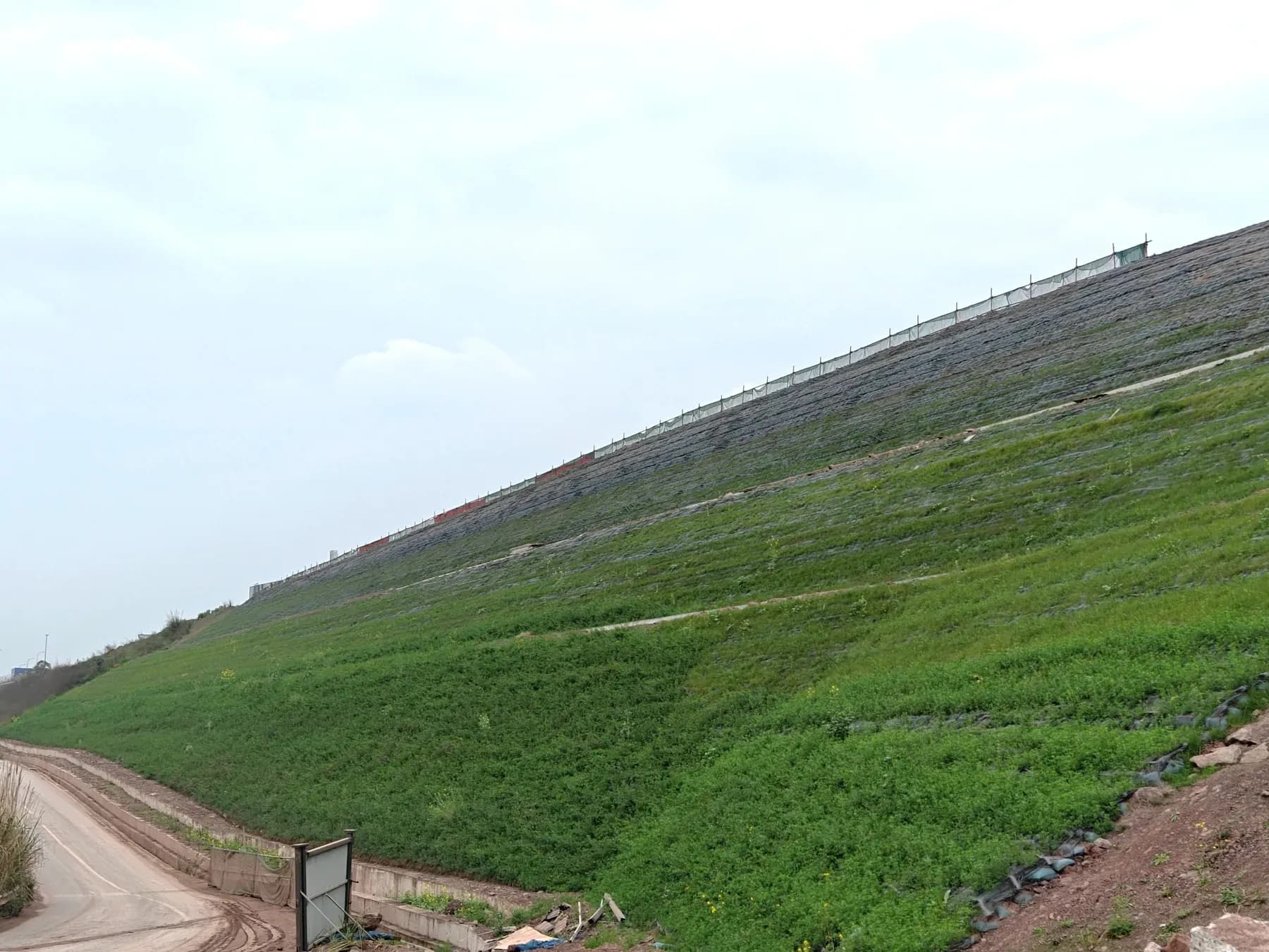
Terraced vegetated reinforced soil slope in flower.SYSTEM RENDER · NOT A PROJECT PHOTO
SYSTEM BUILD-UP

TYPICAL SECTION · VEGETATED REINFORCED SOIL SLOPE

Reinforced soil slope with a vegetated face: layered reinforcement, drainage and protective mesh.

01

VEGETATED SLOPE FACE

with protection net

02

PRIMARY REINFORCEMENT

HG-U geogrid · 0.5 m spacing

03

REINFORCED FILL

compacted in layers

04

DRAINAGE LAYER

500 mm crushed stone

05

BENCHED EXCAVATION

bench ≥ 2 m

06

FOUNDATION SOIL

HLG · F-01 · TYPICAL SECTION · VEGETATED REINFORCED SOIL SLOPE 10.0 m11.1 m21.6 m L = 11.0 m L = 20.0 m 1V : 0.75H 1V : 0.75H VEGETATED SLOPE FACE with protection net SECONDARY REINFORCEMENT short BENCH DRAIN 0.4 × 1.0 m · at 10 m DRAINAGE PIPE φ10 TOE WALL and drainage ditch DRAINAGE LAYER 500 mm crushed stone BENCHED EXCAVATION bench ≥ 2 m CREST DRAINAGE DITCH CLAY SEAL 0.5 m PRIMARY REINFORCEMENT HG-U geogrid · 0.5 m spacing TRI-AXIAL GEOGRID HG-T REINFORCED FILL compacted in layers FILTER LAYER geotextile and stone 0.4 m BACKFILL and original ground GROUNDWATER LEVEL FOUNDATION SOIL TYPICAL SECTION · VEGETATED REINFORCED SOIL SLOPERedrawn from the construction drawing of a completed project · levels, borehole numbers and chainage removedHLG · F-01 LEGEND Primary reinforcement Secondary reinforcement Reinforced fill Crushed stone · drainage Original ground / backfill C20 / C25 plain concrete Section redrawn from the construction drawing of a completed project; levels, borehole numbers and chainage removed. Number of reinforcement layers, reinforcement length, slope steepness and drainage detailing are determined by project-specific design.

◀ drawing is wider than the screen · scroll ▶

TYPICAL SECTION · VEGETATED REINFORCED SOIL SLOPE TYPICAL SECTION · VEGETATED REINFORCED SOIL SLOPE L = 11.0 m L = 20.0 m 1V : 0.75H 1V : 0.75H 1 2 3 4 5 6 1 VEGETATED SLOPE FACE with protection net 2 PRIMARY REINFORCEMENT HG-U geogrid · 0.5 m spacing 3 REINFORCED FILL compacted in layers 4 DRAINAGE LAYER 500 mm crushed stone 5 BENCHED EXCAVATION bench ≥ 2 m 6 FOUNDATION SOIL Redrawn from the project construction drawing; levels and borehole numbers removed. Layer count, reinforcement length and drainage are set by project-specific design.
HLG · F-01Redrawn from the construction drawing of a completed project · levels, borehole numbers and chainage removed

SYSTEM CAPABILITY

What the system can do and what one completed object did are different quantities, so they stay in separate columns.

PARAMETERSYSTEM CAPABILITYCOMPLETED PROJECT
SLOPE STEEPNESSup to 1V:0.5H≈63°1V : 0.75H
HEIGHTby designset by soil, loads and engineering calculation21.6 mtwo benches, 10.0 m and 11.1 m
REINFORCEMENTHG-U geogriduni-axialL = 11.0 / 20.0 m0.5 m spacing

Values depend on soil, fill, groundwater, loads and engineering calculation.

Number of reinforcement layers, reinforcement length, slope steepness and drainage detailing are determined by project-specific design.

SEND YOUR PROJECT DATA

Send your project data for a preliminary engineering assessment.

DISCUSS YOUR PROJECT