ENGINEERING SOLUTION

FOUNDATION STABILISATION

Foundation system, loads and materials.

≈50%*
GRANULAR LAYER THICKNESS OPTIMISATION
50/50 kN/m
HG-B BIAXIAL TENSILE STRENGTH
* Engineering calculation is required for each specific project.
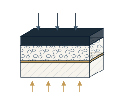
F-05 · GROUND STABILISATION MECHANISM · TRIAXIAL GEOGRID GROUND STABILISATION MECHANISM · TRIAXIAL GEOGRIDLayer build-up and the three working mechanisms of HG-THLG · F-05 1 2 3 4 5 1SURFACE COURSEasphalt or concrete 2GRANULAR LAYERcrushed stone, graded aggregate 3HG-T GEOGRIDtriaxial, at the base of the granular layer 4SUBBASEgranular material 5SOFT SUBGRADEnatural soil Wheel load Load distribution THREE MECHANISMS A AGGREGATE INTERLOCK Triangular apertures engage the aggregate particles. B LATERAL CONFINEMENT Ribs restrain lateral spreading of the granular layer. C LOAD DISTRIBUTION Load is transferred over a wider area of the subgrade. LEGEND Surface course Granular layer HG-T geogrid Subbase Soft subgrade Load distribution Mechanism diagram. Layer thicknesses are indicative and are not design values. Layer composition and thickness, geogrid type and depth are determined by calculation for each project.

◀ drawing is wider than the screen · scroll ▶

F-05 · GROUND STABILISATION MECHANISM · TRIAXIAL GEOGRID HLG · F-05 GROUND STABILISATION MECHANISM · TRIAXIAL GEOGRID Layer build-up and the three working mechanisms of HG-T 1 2 3 4 5 1 SURFACE COURSE asphalt or concrete 2 GRANULAR LAYER crushed stone, graded aggregate 3 HG-T GEOGRID triaxial, at the base of the granular layer 4 SUBBASE granular material 5 SOFT SUBGRADE natural soil THREE MECHANISMS AAGGREGATE INTERLOCK Triangular apertures engage the aggregate particles. BLATERAL CONFINEMENT Ribs restrain lateral spreading of the granular layer. CLOAD DISTRIBUTION Load is transferred over a wider area of the subgrade. Mechanism diagram. Layer thicknesses are indicative and are not design values. Layer composition and thickness, geogrid type and depth are determined by calculation for each project.
HLG · F-05Layer build-up and the three working mechanisms of HG-T

ENGINEERING APPROACH

FROM PROJECT CONDITIONS TO A SYSTEM SOLUTION

Configuration is defined by the conditions of the specific project.

PROJECT CONDITIONS

  1. GROUND

  2. LOADS

  3. GEOMETRY AND DRAINAGE

ENGINEERING ASSESSMENT

  1. FUNCTION
  2. MATERIAL
  3. CONFIGURATION

FOUNDATION SYSTEM

HG-T · LAYER OPTIMISATION
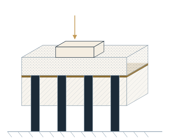
HG-B · LOAD TRANSFER

The final configuration is confirmed by engineering calculation.

TECHNICAL DIRECTIONS

TWO SYSTEM TYPES FOR ONE ENGINEERING TASK

Selection is driven by the site conditions, loading and calculation.
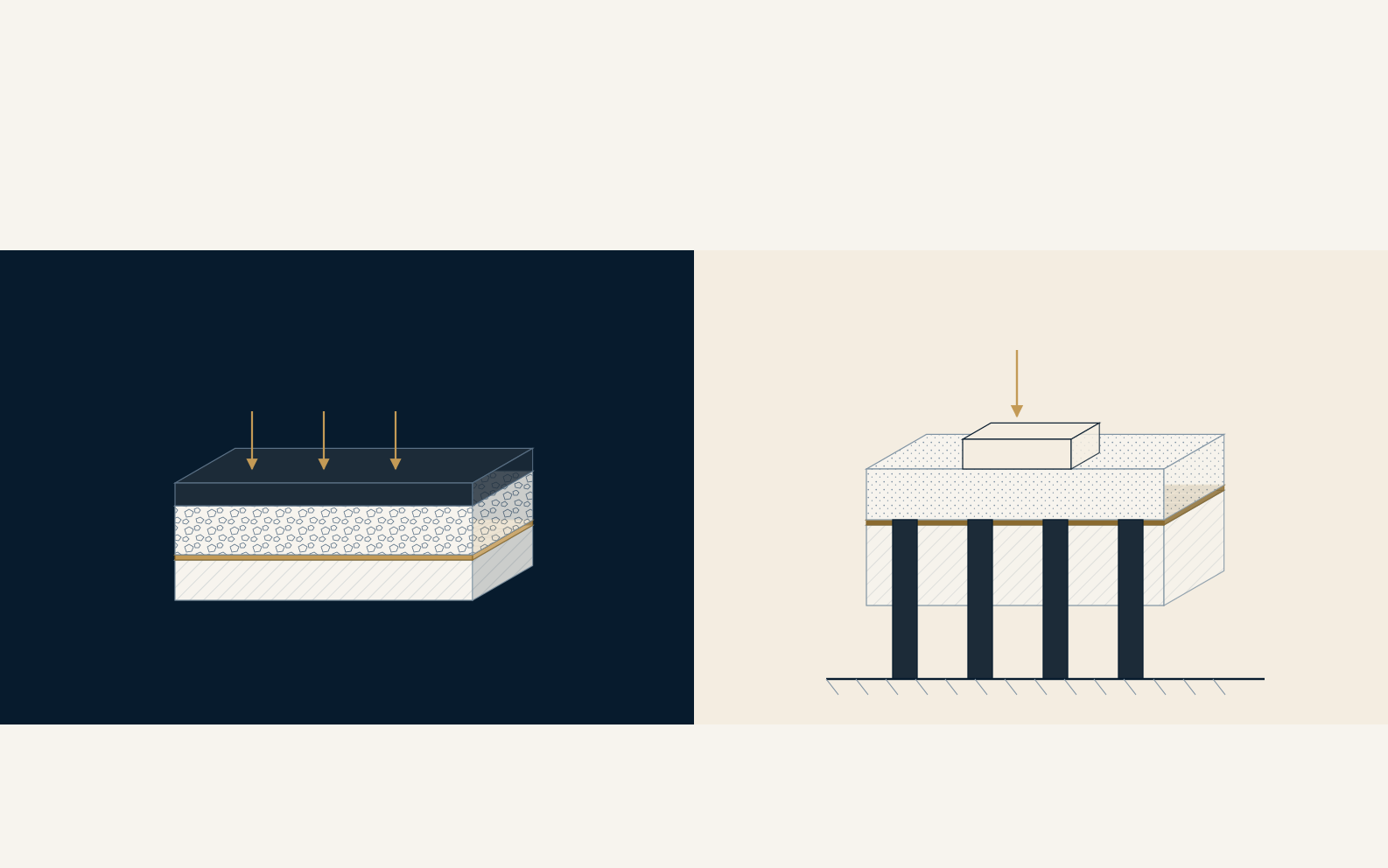
HG-T

GRANULAR LAYER STABILISATION

ROAD BASES · WORKING PLATFORMS
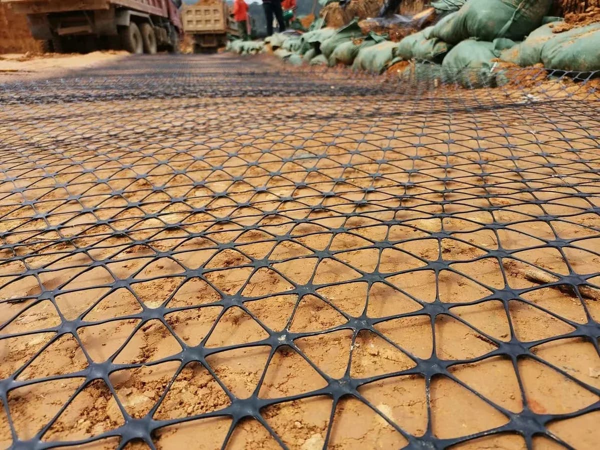
Close view of triaxial geogrid: triangular apertures and rib nodes.
HG-T material

HG-B

LOAD TRANSFER AND REINFORCEMENT

PILE-SUPPORTED PLATFORMS · LOADED FOUNDATIONS
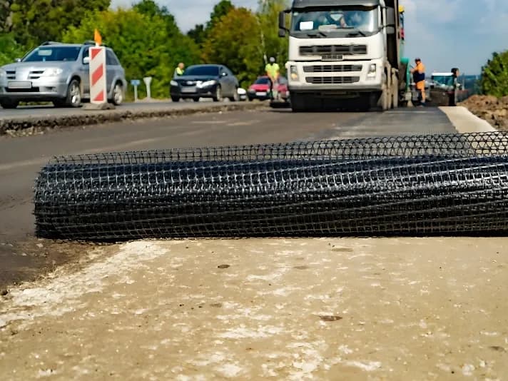
Roll of biaxial geogrid set out on the road base before laying.
HG-B material
DISCUSS PROJECT CONDITIONS

The final configuration is confirmed by engineering calculation.

APPLICABLE PRODUCTS

Typical ground conditions, the function the reinforcement performs, and the geogrid used in each.

WORKING CONDITIONWHAT THE REINFORCEMENT DOESPRODUCT
Road and pavement basesAggregate interlock and lateral confinement in the granular layer.HG-T
Working platformsConfinement of the platform layer under tracked and wheeled plant.HG-T
Weak subgradeLoad spreading over a wider area; control of differential settlement.HG-T / HG-B
Pile-supported groundLoad transfer from the fill onto the pile caps.HG-B

Values shown are nominal and subject to change without notice. Project-specific values shall be confirmed by Harland Geo prior to design or supply.
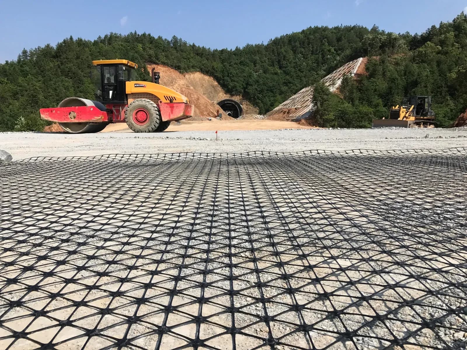
  • Triaxial geogrid laid across a prepared formation over a wide area and compacted by roller.
    Triaxial geogrid · granular layer compaction
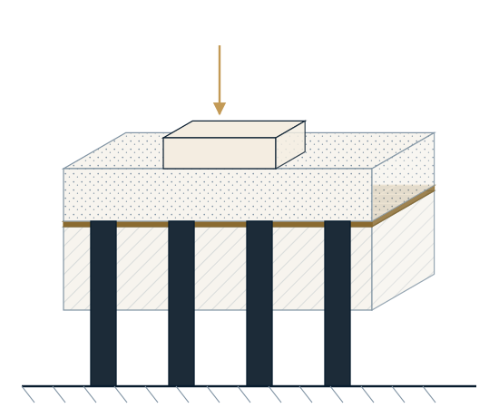
  • Drawing of pile-supported ground: fill over a biaxial geogrid on the pile caps, carrying the load down onto the piles.
    Biaxial geogrid · load transfer onto pile caps