Reinforced Soil Structures

REINFORCED SOIL STRUCTURES

Flexible systems for slopes, retaining walls and embankments.

APPLICATION EXAMPLES
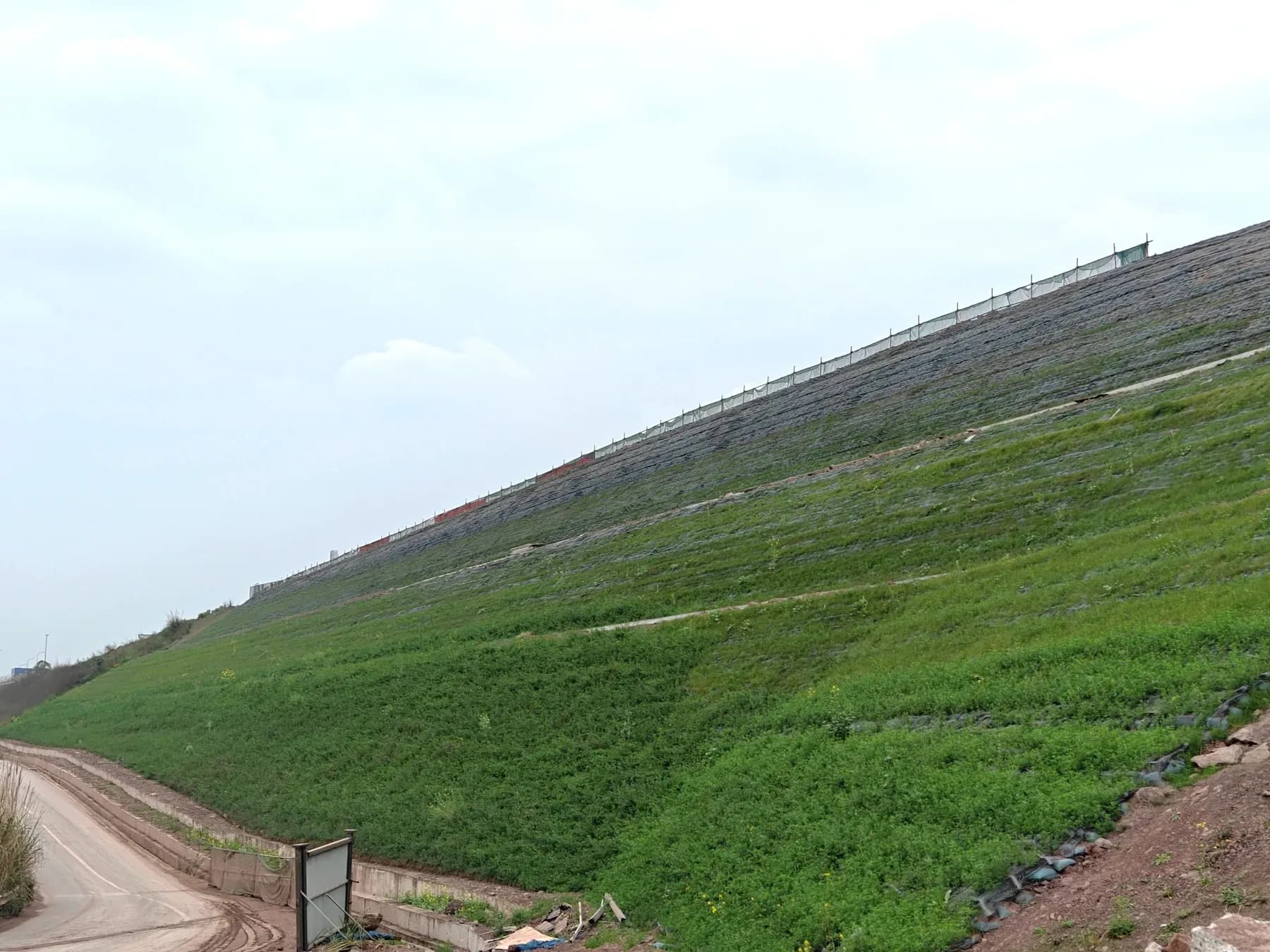
  • Reinforced soil slope with a fully established vegetation cover over the whole face.

    Vegetated Reinforced Slope

    Reinforced soil slope with a vegetated face: layered reinforcement, drainage and protective mesh.

    APPLICABLE PRODUCTS

    FACE STEEPNESS
    up to 1V : 0.5H ≈ 63°
    GEOGRID
    HG-U primary · HG-T tri-axial
    VIEW SYSTEM
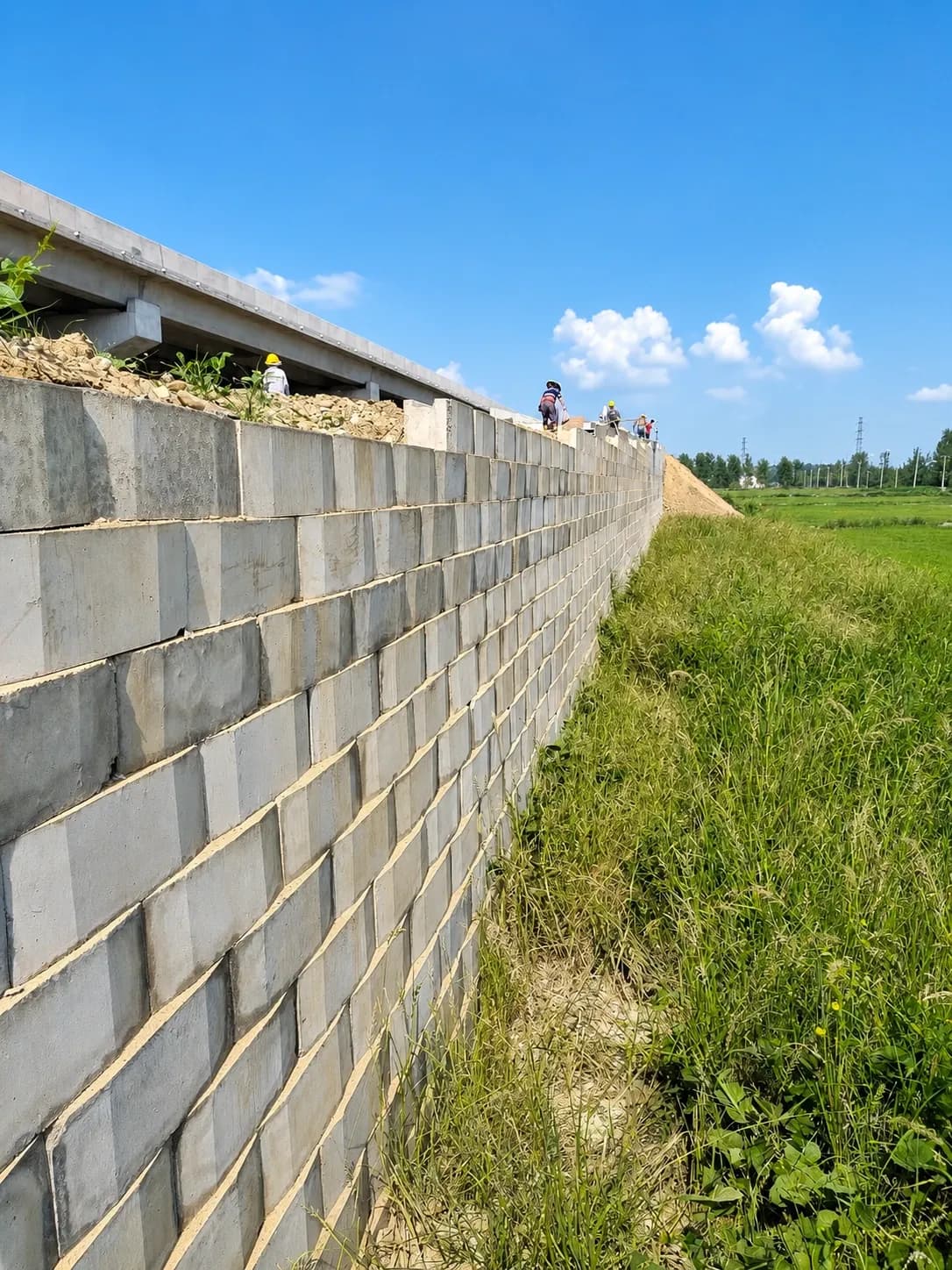
  • Completed modular block retaining wall on a client project, running alongside a grassed embankment.

    Modular Retaining Wall

    Retaining wall of precast modular units with geogrid cast into the unit, backed by a reinforced soil mass.

    APPLICABLE PRODUCTS

    FACE STEEPNESS
    up to 1V : 0.02H ≈ 88.9°
    GEOGRID
    HG-U primary · HG-T under pavement
    VIEW SYSTEM
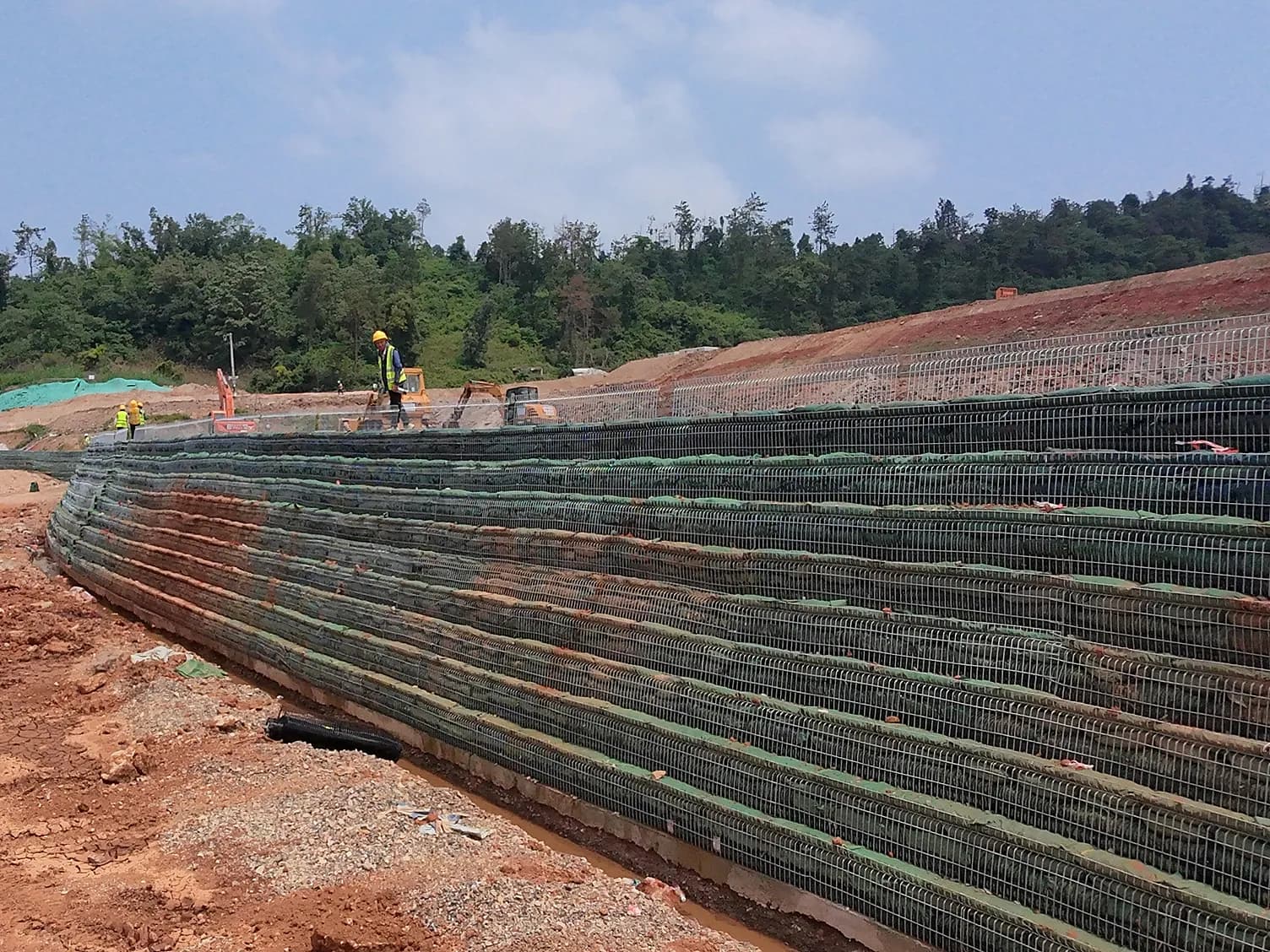
  • Steel mesh faced reinforced soil wall under construction on a curved alignment, built up in wrapped lifts to the design face.

    Steel Mesh Faced Reinforced Soil

    Reinforced soil structure with steel mesh facing panels and rock fill.

    APPLICABLE PRODUCTS

    FACE STEEPNESS
    70° – 85°
    GEOGRID
    HG-U primary · polymer connectors
    VIEW SYSTEM
  • STRUCTURAL PERFORMANCE

    Loads, stability and service conditions are assessed for each structure.

  • DESIGN FLEXIBILITY

    Adaptable to site conditions, structure height and application.

  • MODULAR CONSTRUCTION

    Modular systems are assembled in repeating lifts as construction proceeds.

PROJECT INPUTS

  • GEOMETRY
  • LOADS
  • SOIL / WATER
  • FILL
  • FACING
  • STANDARDS

Send your project data for a preliminary engineering assessment.

DISCUSS YOUR PROJECT
HLG-F-02 · REINFORCED SOIL SYSTEM · GENERAL SECTION 1 2 3 4 5 6 7 8 9 10 1FACING SYSTEM options below 2PRIMARY REINFORCEMENT HG-U geogrid, connected at the facing 3SECONDARY REINFORCEMENT short, starting at the facing 4DRAINAGE AND FILTER behind the facing, with outlet 5LEVELLING PAD embedded below finished grade 6HG-T GEOGRID under the pavement 7LOW-PERMEABILITY CAP over fill and drainage zone 8REINFORCED FILL compacted in layers 9BENCHED EXCAVATION into original ground 10COMPACTED FOUNDATION REINFORCED SOIL SYSTEM · GENERAL SECTION System build-up and three facing options HLG · F-02 FACING OPTIONS VEGETATED SLOPE up to 1V : 0.5H ≈ 63° Vegetation cover and protection net STEEL MESH FACING 70° – 85° Rock-filled units and polymer connectors MODULAR FACING up to 1V : 0.02H ≈ 88.9° Concrete modules with pre-embedded geogrid LEGEND Primary reinforcement Secondary reinforcement Reinforced fill Crushed stone · drainage Original ground Concrete System build-up diagram. Geometry, reinforcement length and spacing, drainage and facing detailing are determined by project-specific design. The steepness values shown are system capability limits under suitable soil, fill, groundwater, loading and engineering calculation.

◀ drawing is wider than the screen · scroll ▶

HLG-F-02 · REINFORCED SOIL SYSTEM · GENERAL SECTION REINFORCED SOIL SYSTEM GENERAL SECTION HLG · F-02 1 2 3 4 5 6 7 8 9 10 1 FACING SYSTEM options below 2 PRIMARY REINFORCEMENT HG-U geogrid, connected at the facing 3 SECONDARY REINFORCEMENT short, starting at the facing 4 DRAINAGE AND FILTER behind the facing, with outlet 5 LEVELLING PAD embedded below finished grade 6 HG-T GEOGRID under the pavement 7 LOW-PERMEABILITY CAP over fill and drainage zone 8 REINFORCED FILL compacted in layers 9 BENCHED EXCAVATION into original ground 10 COMPACTED FOUNDATION FACING OPTIONS VEGETATED SLOPE up to 1V : 0.5H ≈ 63° Vegetation cover and protection net STEEL MESH FACING 70° – 85° Rock-filled units and polymer connectors MODULAR FACING up to 1V : 0.02H ≈ 88.9° Concrete modules with pre-embedded geogrid System build-up diagram. Geometry, reinforcement, drainage and facing are determined by project-specific design.
HLG · F-02System build-up and three facing options